
Pad Printing Machine for Electronics Components Manufacturer Guide
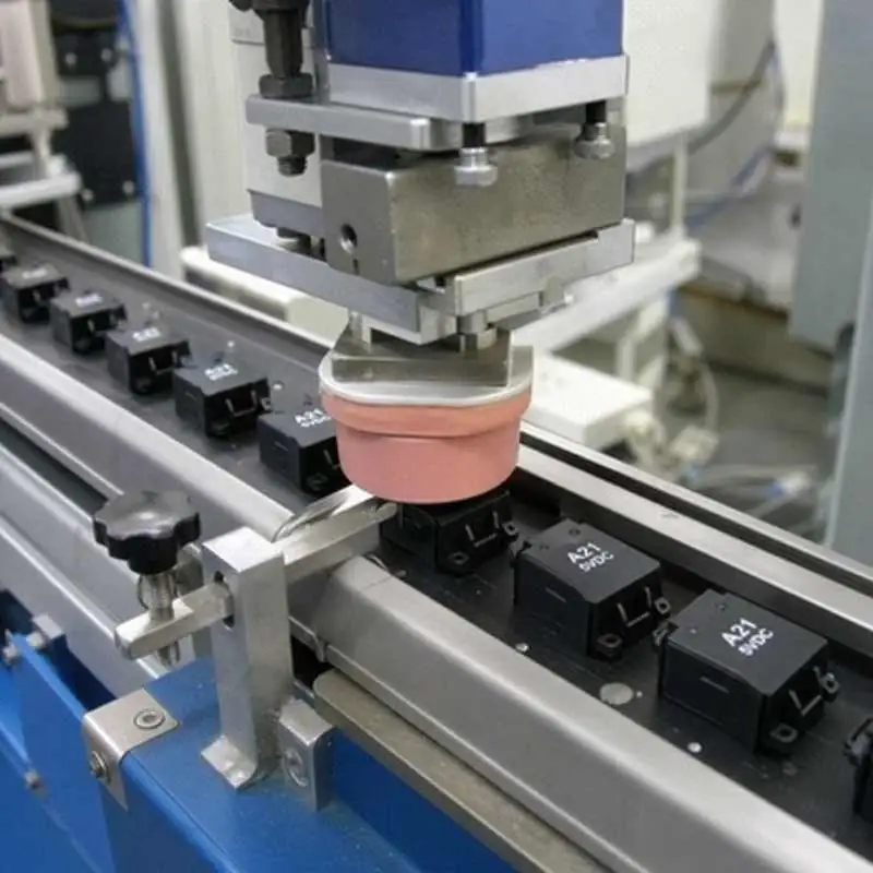
Electronics manufacturers live and die by traceability, legibility, and throughput. Whether you’re marking ICs, connectors, keycaps, shields, housings, or fully assembled PCBs, a Pad Printing Machine for Electronics remains one of the most flexible ways to put crisp graphics, alphanumerics, and 2D codes onto challenging surfaces. This Pad Printing Machine for Electronics Components Manufacturer Guide focuses on practical decision-making: process capability, tooling, ink, automation, and quality controls—so you can spec equipment confidently and avoid costly trial-and-error.
Table of Contents
Why pad printing is still the workhorse for electronics marking
Pad printing transfers ink from an etched plate (cliché) to a silicone pad, then onto the part. For electronics, it excels when parts are:
- Small and three-dimensional (curved, textured, recessed, stepped)
- Low mass and fixture-dependent (connectors, SMD reels, molded housings)
- Material-diverse (PC, ABS, PBT, nylon, LCP, metal shields)
- Cosmetic + functional (logos, pin-1 dots, polarity marks, compliance icons)
Common pad printing applications include:
- IC package logo printing (logo + date code + lot on molded packages)
- PCB pad printing equipment use cases (legend-style marks, keep-out labels, conformal-coat indicators)
- Switch/keycap legends, connector IDs, shield can marks, adapter housing graphics
- CE RoHS compliant marking on enclosures or product labels (confirm your exact regulatory marking rules for your product category)
If you’re comparing pad printer vs laser marking, pad printing usually wins on:
- Lower upfront cost for multi-station lines
- Better on certain plastics where laser contrast is poor
- True multi-color graphics and solid fills (especially with two-color pad printing setup)
Laser often wins on permanent engraving and variable data without plates—more on this later.

Where pad printing fits in an SMT component marking process
In many factories, marking happens either:
- Pre-SMT (on housings, leadframes, connector bodies, trays), or
- Post-SMT (after placement/reflow, on assemblies or PCB subassemblies)
For a typical SMT component marking process, pad printing is most stable when:
- Heat exposure is controlled (post-reflow marking avoids ink going through reflow)
- The mark locati0n is not later covered by adhesive, potting, or conformal coat
- Fixturing ensures repeatability across board warp and panel tolerances
Actionable tip: if you need variable data (serials) on every board, consider hybrid flow—pad print the fixed logo/compliance icons, then laser or label for serialization.
How to choose pad printer: the decision checklist (what actually matters)
When people ask how to choose pad printer, they often focus on machine size. For electronics, the real differentiators are repeatability, micro-feature print capability, automation readiness, and process control.
1) Required precision and print size
Define:
- Smallest line/character height
- Solid-fill area vs fine strokes
- Acceptable misregistration and smudge limits
For precision pad printing tolerance, be realistic: your system tolerance stack includes:
- Fixture datums + part variation (molding shrink, warpage)
- Pad deformation and rebound
- Plate etch quality
- Ink viscosity drift over time
- Robot/conveyor indexing accuracy (if automated)
Practical guidance: if you must hit extremely tight registration across multiple colors, prioritize servo-driven axes, closed-loop indexing, and a robust two-color pad printing setup with precise pad-to-part alignment features.
2) Manual, semi-auto, or automated pad printing
- Manual: best for prototypes and low-mix/low-volume.
- Semi-auto: good for stable SKUs with moderate volume.
- Automated pad printing: essential for high-volume electronics with traceability and reduced handling.
For automation, look for:
- Part presence sensors and vision-ready mounting
- Recipe control (plate, pad, stroke, dwell, speed)
- Ethernet/IP, Profinet, or standard I/O for line integration
- Guarding and interlocks for safety compliance
Don’t just buy a machine—plan automation integration for pad printers including:
- Conveyor or dial table
- Buffering for upstream/downstream variation
- Reject/verification station (vision)
- OEE data capture

3) Ink cup vs open ink well
For electronics, sealed ink cup systems often help:
- Reduce solvent evaporation → stable viscosity
- Improve cleanliness around sensitive assemblies
- Lower VOC exposure and housekeeping time
Open inkwells can still be appropriate for special inks or large-format prints, but they demand stricter operator control.
Ink, adhesion, and “pad printing ink for plastics” done right
Selecting pad printing ink for plastics is usually the make-or-break factor. In electronics, you’re commonly printing on PC/ABS, PBT, PA, LCP, and filled materials. Requirements typically include abrasion resistance, alcohol wipe resistance, and sometimes high temperature aging.
Key variables:
- 1K vs 2K inks (2K often improves chemical resistance and adhesion)
- Solvent system and drying time
- Pigment opacity (especially on dark housings)
- Post-cure needs (air dry vs heat cure)
Surface preparation options:
- Corona/plasma treatment for low-surface-energy plastics
- Primer systems (only if compatible with downstream processes)
- Cleanliness control (mold release, fingerprints, silicone contamination)
Actionable tip: lock a simple control plan—ink batch, mix ratio, pot life tracking, viscosity checks per shift, and a standardized adhesion test (cross-hatch, tape pull, or rub test).
Silicone pad hardness selection: shape, durometer, and longevity
Silicone pad hardness selection affects detail transfer, coverage, and wear.
- Softer pads (lower Shore A): better conformity on textured/curved surfaces; risk of distortion on fine features.
- Harder pads: sharper detail; less conformity; can struggle on deep recesses.
Choose pad geometry based on:
- Print area size and part curvature
- Need to avoid “air traps” on recessed logos
- Clearance around tall features (pins, bosses)
Pad life tips:
- Use proper pad cleaning (tape clean or automated pad cleaner)
- Avoid over-compression (set stroke limits)
- Rotate pads between stations in multi-shift operations

Tooling that controls everything: fixture design for small parts
In electronics, your pad printer is only as accurate as your tooling. Fixture design for small parts should be treated like metrology tooling, not “simple nests.”
Best practices:
- Reference on functional datums (not cosmetic edges)
- Use kinematic locati0n principles where possible (3-2-1)
- Add positive retention (vacuum, magnets, light clamping) without part deformation
- Provide poka-yoke loading and orientation control
- Design for cleanability (flux, dust, ink mist)
If printing on PCBs or panels, add:
- Panel stops + fiducial-based alignment (or vision assist)
- Support pins to manage bow/warp
- ESD-safe materials and grounding
Plates, artwork, and multi-color control
For custom pad printing, your artwork and plate-making method determine edge quality.
Consider:
- Plate type (polymer vs steel) depending on volume and solvent
- Etch depth matched to ink system for consistent transfer
- Standardized naming/version control for clichés and artwork
For a stable two-color pad printing setup:
- Minimize time between colors to avoid first-layer contamination
- Use mechanical registration features and test coupons
- Validate overprint behavior (trapping) and opacity
Quality tip: define a “golden sample” and a measurable visual standard (lighting, angle, acceptable defects) to avoid subjective pass/fail on the floor.
Pad printer vs laser marking: choosing by application
A practical comparison:
Pad printing advantages:
- Best for logos, icons, filled shapes, multi-color
- Works well on many plastics without special additives
- Lower per-part cost for stable designs at volume
Laser advantages:
- Variable data without plates (serials, date codes, UID)
- Very durable marks (depending on substrate)
- Less consumable management (no ink mixing)
Decision rule:
- If your mark is mostly fixed graphics and you need color/opacity → pad printing.
- If you need unique data per part and extreme permanence → laser or hybrid.
Best pad printing machine brands: how to evaluate (without guesswork)
Instead of relying on a generic “best pad printing machine brands” list, qualify suppliers by objective criteria:
- Proven electronics references (ICs, connectors, PCB assemblies)
- Spare parts availability and lead times
- Local service capability and remote diagnostics
- Automation ecosystem (robots, conveyors, dial tables, vision)
- Documentation (IQ/OQ support if you’re regulated)
- Repeatability specs with real test data, not marketing
Ask for a sample run on your parts with your ink and your required cycle time.

Verification, compliance, and traceability
Electronics customers often require legibility standards and process records.
For compliance-oriented marking (including CE RoHS compliant marking where applicable to your product documentation and labeling plan), implement:
- Print inspection (manual or automated vision)
- Lot traceability for ink, clichés, pads, and parts
- Periodic adhesion/abrasion tests
- Environmental testing if needed (temperature/humidity aging, IPA rub)
If you offer pad printing services (contract marking) or run internal shared lines, standardized recipes and inspection criteria reduce variation across shifts and operators.
Pad printing machine troubleshooting: fastest root-cause map
When quality drifts, use this quick triage for pad printing machine troubleshooting:
- Blurry edges / smearing
- Ink too thin, too much solvent, or humidity effects
- Excessive pad pressure or dwell
- Part not seated; fixture wear
- Incomplete transfer / pinholes
- Ink too thick or drying on plate
- Pad contamination (oil, dust) or wrong durometer
- Etch depth mismatch; worn cliché
- Misregistration
- Fixture datum shift, part variation, loose stops
- Axis backlash or indexing error (automation)
- Multi-color timing/registration not locked
- Poor adhesion
- Wrong ink system for substrate
- Mold release contamination; insufficient surface treatment
- Cure time/temp not met; exceeded pot life
Keep a small “process health” log: viscosity, room conditions, pad cycles, plate age, defect type, and corrective action.
Putting it together: a proven buying spec for electronics manufacturers
When drafting your RFQ for a Pad Printing Machine for Electronics Components Manufacturer Guide-level purchase, include:
- Part list + substrates + surface finish
- Mark content (logo/text/2D), size, and locati0n constraints
- Target cycle time, OEE assumptions, and shift plan
- Automation needs (load/unload, conveyor, dial, robot)
- Inspection method (vision, sampling, traceability)
- Changeover time targets (pads, clichés, fixtures)
- Factory acceptance test criteria on your actual parts
This clarity also helps you decide whether you need in-house capability or outsource to pad printing services.
Conclusion: the best pad printing outcome is engineered, not “tuned”
For electronics, pad printing succeeds when the machine, ink, pad, plate, and fixtures are specified as one controlled system. Focus on automation readiness, repeatability, and tooling discipline—then validate with real parts under real line conditions. Done right, pad printing for electronic components delivers fast cycle times, crisp marks, and stable quality, whether you’re scaling a single SKU or running high-mix production with custom pad printing requirements.